Our Excellent Products

  • Structured Packing
  • Random Packing
  • Tower Internals
  • Others
Structured Packing
metal structured packing random packing
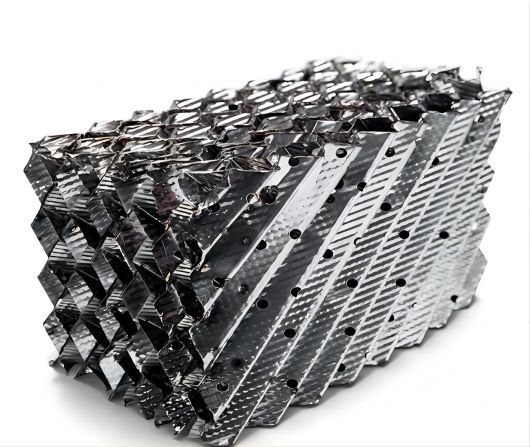
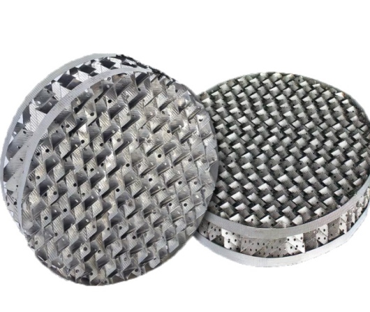
Metal Structured Performated Tower Packing
Structured Packing is a kind of packing arranged and stacked in accordance with uiform geometry in the tower.The geometry of the whole tower section is regular,symmetrical and uniform, and the gas-liquid flow path is specified ,which reduces the phenomeneon of channel flow and wall flow, and the pressure drop can be very small.Under the same energy cost and pressure drop, it can provide more specific suface area than random packing, and achieve higher mass transfer and heat transfer efficiency in the same volume. In recent decades, structured packing has been widely used in many towers in fine chemical industry,perfume industry,oil refining,fertilizer,petrochemical industry and the other fields. Structured packings are available in two different inclination angles,ie. Type X and Type Y. The type Y packings have an inclination and angle of about 45 from the horizontal axis, and are the most widely used.The type X packings have an inclination angle of 30 from horizontal axis and are used in high capacity and low pressure drop applications.
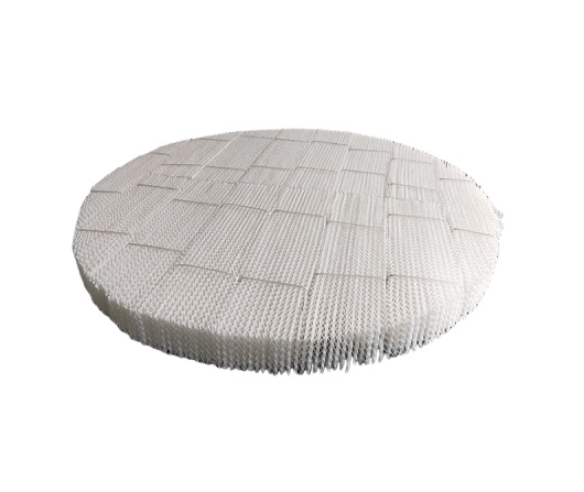
Plastic perforated structured packing
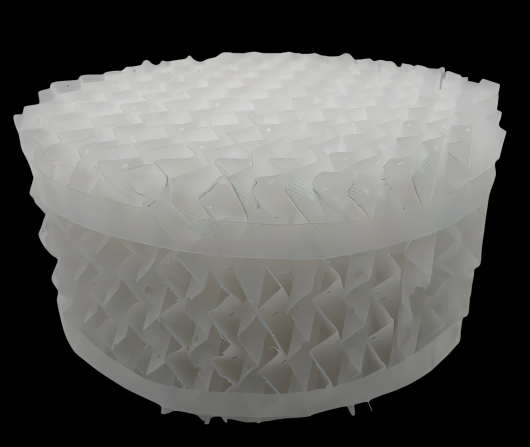
Plastic Corrugated Plate Packing Tower Packing
Since Metal Mellapak was be developed & accepted by market. Scientists find Metal Corrugated plate packing was not suitable in any medium’ s requirement  (acid). Furthermore, it is very hard to widely used in industry field. After that, Plastic Corrugated plate packing was born. Compared with Metal Corrugated plate packing, it has large flux, low pressure drop,large surface area and so on.  
ceramic honeycomb high efficiency gas purification
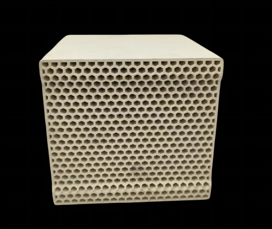
Honeycomb Zeolite Molecular Sieve High Efficiency Waste Gas Purification
At present, VOCs treatment mainly uses activated carbon. Since activated carbon cannot be analyzed at high temperature, it is replaced regularly. However, activated carbon adsorbed with organic matter is a dangerous chemical with high processing cost.This environmentally friendly adsorbent material is hydrophobic molecular sieve, which is different from ordinary molecular sieve in that it preferentially adsorbs water in gas. It has a highly selective adsorption capacity for organic matter, and can be resolved at high temperature, thus realizing continuous adsorption-regeneration.The adsorption material is made into a cellular structure by a special preparation process. The adsorption capacity of organic matter is more than 2%, which can be adsorbed and regenerated for a long time. Honeycomb Molecular Sieve adopt adsorption system to reduce exhaust gas concentration and air volume, and at the same time cooperate with catalytic combustion technology to reduce operating cost.  
wire mesh structured packing
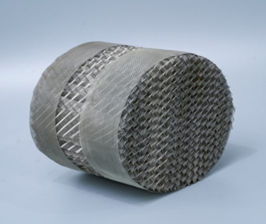
Wire Mesh Structured Packing Tower Packing
Wire mesh structured packing has a high specific surface area. At the same time, because of the unique capillary effect of the mesh. The packing surface has better wettability. So it has a high separation efficiency. Compared with other types of packing, it has lower pressure drop and less liquid holding, and it is especially suitable for materials hard to separate and heat sensitive systems. The main materials for making wire gauze packing are stainless steel, copper, aluminum, iron, nickel, etc.   
plastic structured packing
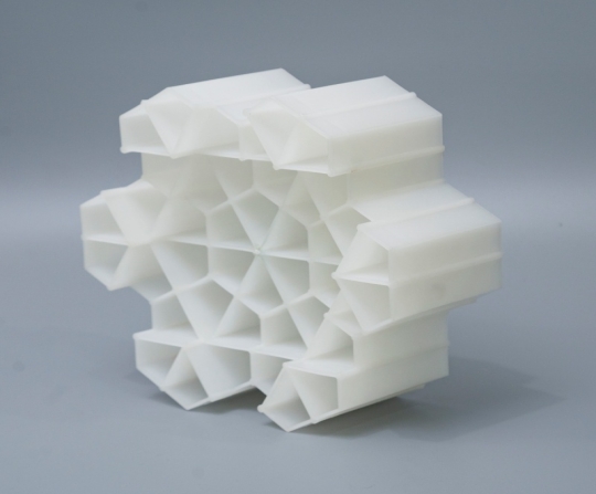
Honeycomb shape plastic support block
Honeycomb shape plastic support block is made of synthetic plastic injection molding. The formula can be adjusted according  to different working conditions to achieve the best effect. It completely replaces the light ceramic packing commonly used  before. The honeycomb shape plastic support block developed by us can be used repeatedly, with large specific surface area  and large ventilation capacity, and its effectiveness is twice that of light porcelain. Especially in the process of maintenance, the  light ceramic packig becomes solid waste, which is difficult to deal with. But honeycomb shape plastic support block can be  reused as renewable resources, which is environmental protection and energy saving. Through the long-term test of Coking  Desulfurization Tower. It is proved that honeycomb shape plastic support block has strong anti blocking ability and excellent  separation and purification effect.        
pph perforated structured packing
PPH Corrugated Plate Packing Tower Packing
Since Metal Mellapak was be developed & accepted by market. Scientists find Metal Corrugated plate packing was not suitable in any medium’ s requirement  (acid). Furthermore, it is very hard to widely used in industry field. After that, Plastic Corrugated plate packing was born. Compared with Metal Corrugated plate packing, it has large flux, low pressure drop,large surface area and so on.  
252Y structured packing manufacturers
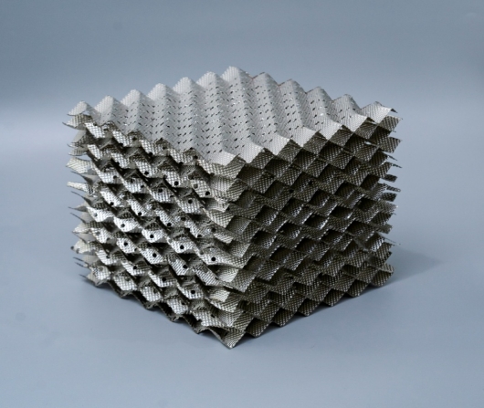
Type 252Y Stainless Steel Perforate Corrugated Plate for Structured Packing
The geometric structure will provide a large specific surface area. The capillary function of the screen also increases the wettability of the surface area. When filling, the upper and lower packing trays cross 90°, which has the advantages of high efficiency, reduced pressure and large flow. It is used in vacuum distillation, atmospheric distillation and the absorption process of difficult to separate or heat sensitive substances.  
copper structured packing column
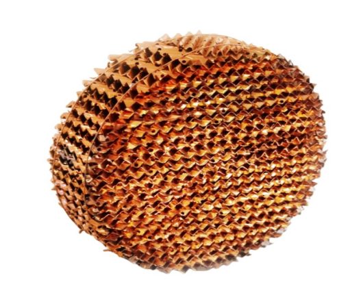
Copper Metal Orifice Plate Corrugated Packing
It is formed from corrugated sheets of perforated embossed metal or wire gauze. The result is a very open honeycomb structure with inclined flow channels giving a relatively high surface area but with very low resistance to gas flow. The surface enhancements have been chosen to maximize liquid spreading. These characteristics tend to show significant performance benefits in low pressure and low irrigation rate applications. Metal Structured Packing is manufactured in a wide range of sizes by different crimp altitude. The Packing Surface ranges from 50 m²/m³ (lowest efficiency, highest capacity) to 750 m²/m³ ( highest efficiency, lowest capacity ). 
Random Packing
metal tower packing
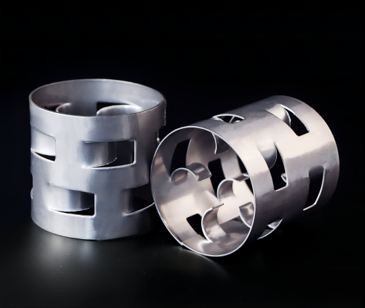
High Performance Metal Random Packing Metal Pall Ring
It was invented by German BASF, the first generation  Random packing. To compared with Raschig ring, the most important improvement is increase two row of inward ligule. It promotes liquid-gas liquidity and improve tower’ s packing’ s mass transfer performance.  
High performance ceramic pall ring
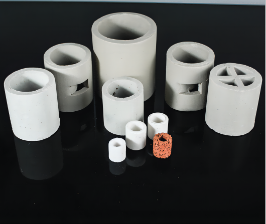
Random Packing Ceramic Pall Ring
It was invented by German BASF, the first generation  Random packing. To compared with Raschig ring, the most important improvement is increase two row of  inward ligule. It promotes liquid-gas liquidity and improve tower’ s packing’ s mass transfer performance.  
metal cascade ring tower packing
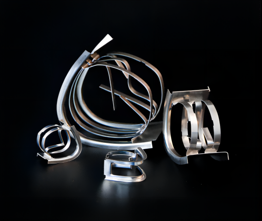
Metal Intalox Saddle Ring Tower Packing
Owing to this pack’ s shape is like saddle, so called saddle ring or Berl Ring. The earliest saddle ring’ s material is ceramic. In our actual application, when gas flows upward, liquid will flow downward along with arc channel. This Movement way will directly reduce wall flow’ s happening. However, Arched external frame also cause overlapping & bridging .Therefore, scientists change two ends into rectangle type contact surface. This improvement will reduce bridging’ happen.  
raschig ring
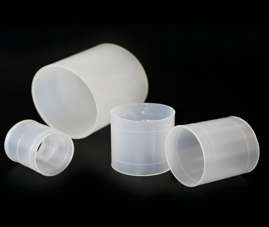
Plastic Raschig Ring Tower Packing
It is a earliest development of random packing, which its height is equal to outside diameter. Raschig Ring was invented by German Chemist Friedrich Raschig in 1914, it also marks that the development of fills hds entered a scientific track. However, in the actual application, Such as ” Wall flow, Channel flow and so on” often happened in Packed bed.  
plastic snowflake ring tower packing
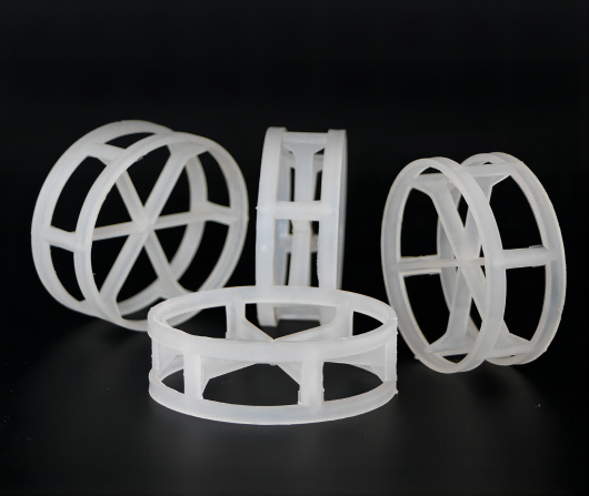
Plastic Snowflake Random Packing Tower Packing
Plastic snowflake ring is a high-effciency tower packing which was named byb its shape.lt has a low specifc gravity, high flooding point, large porosity, high mass transfer unit height.Besides, this random packing has lower pressure drop, which reduces the back-pressure phenomenon and minimizes the energy consumption of the stripping process.Plastic snowflake ring is very economical.it can be applied in the chlorine and bromine production,air separation and water cooing process.  
plastic flat ring
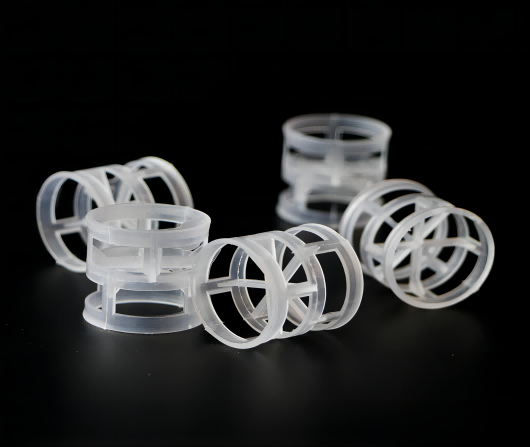
Plastic Flat Ring Tower Packing
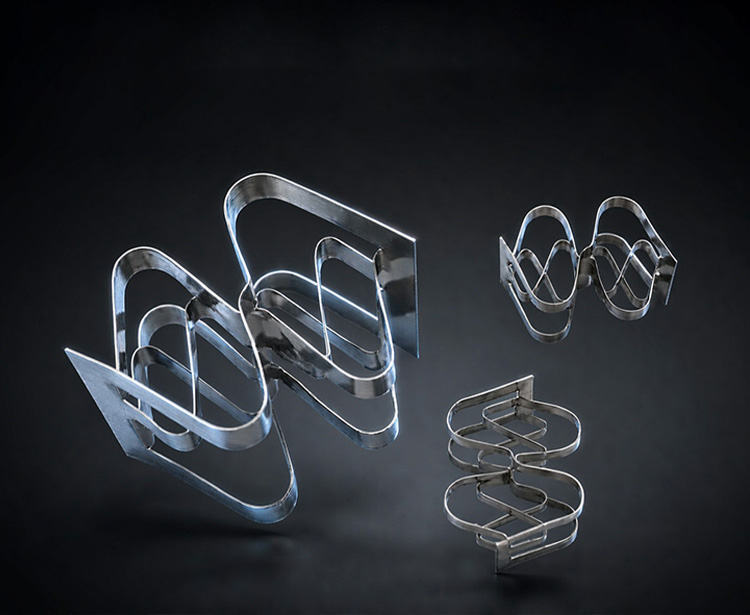
Flat ring is also called SMR(Super Mini Ring), It s an advanced random packing in the column tower packing. It has similar structure with cascade mini ring, There is not flanging structure at the top and bottom. It can improve the packing strength through adjust the arc of internal blade. It has reasonable flow structure, low pressure drop and high mass transfer performance. Super mini ring has two main types, which names as QH-1 and QH-2.  
plastic super saddle ring tower packing
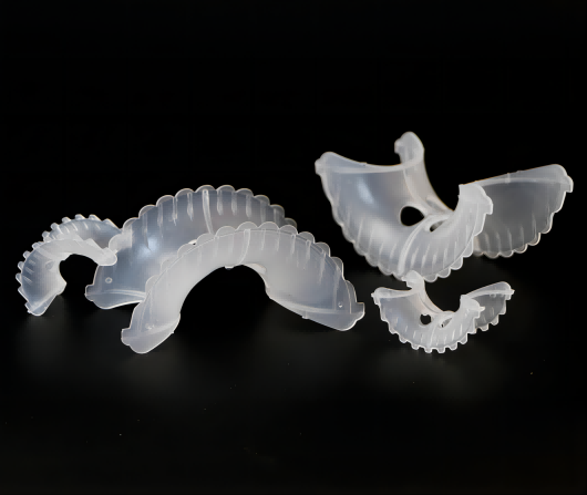
Plastic Super Saddle Ring Tower Packing
It was one improved ring based on Intalox ring’ s structure. The biggest improvement is that Intalox saddle’ s arc profile will be change wavy or jagged profile. meanwhile, increase some pores in the arc liquid channel’ s middle position. This structure’ s change not only increase packing’ s contacting gap, but also improve gas & liquid’ s movement and distribution in packing layer
plastic ralu ring tower packing
Plastic Ralu Random Packing Tower Packing
This is an improved pall ring. The main improvement is to increase the turning over and wall thickness at both ends. Without changing the separation efficiency, the bed height can be reduced. So as to reduce the pressure drop..
Tower Internals
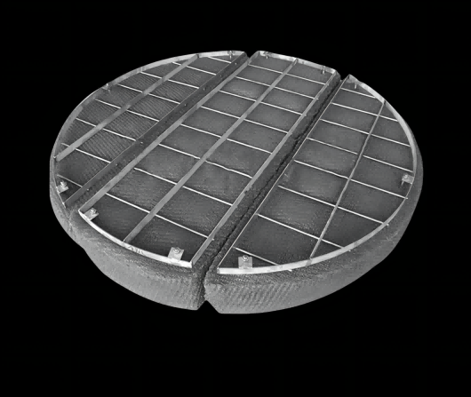
Knitted Wire Mesh Demister Wire Mesh Mist Eliminator
A complete range of mist elimination devices including mesh pad demisters ,vane type mist eliminators and liquid coalescers for separation of entrained liquids are offiered. Products are available in a variety of metals, plastics and thermoplastics for a wide range of applications.Mist eliminators are employed at the top of a packed column or in conjunction with a collecting tray between two packed beds. They separate liquid droplets from the gas stream. Droplet discharge from the column and/or the liquid entrainment from one stage to the next is minimized. Our mist eliminators are engineered for optimal performance under specific applications.  
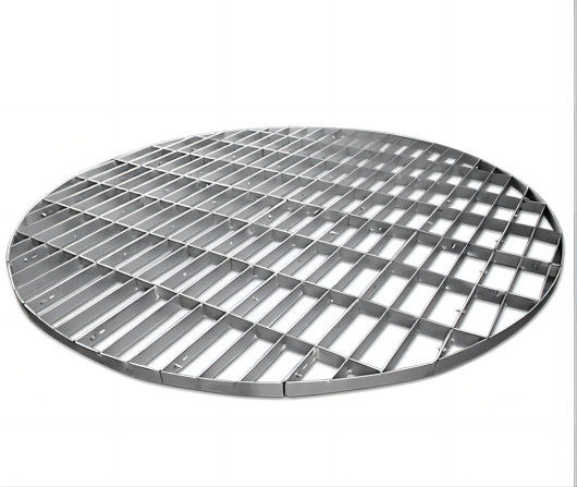
Support Grid Plate
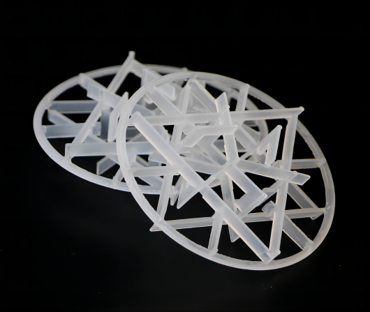
Distillation Column Random Packing Support Grid Plate
The support grid plate has to be constructed in a way that it allows flow of gases and liquids in the column as unrestricted as possible. This is especially important in the area between support grid and packed bed there is the danger of blocking the gas flow by an unsuitable packing support. The main function of these devices is to support the tower packing bed structurally. Support grids work in both structured and random packing processes for a wide range of purposes.  
plastic bubble cap tray
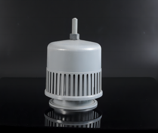
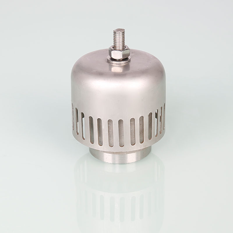
Plastic Bubble Cap For Chemical Industry
Bubble cap tray is a flat perforated plate with risers (like pipes) around the perforations, and caps in the form of inverted cups over the risers.The caps are usually equipped with slots or holes through which vapor comes out. The cap is mounted so that there is a space between riser and cap to allow the passage of vapor. Vapor rises through the riser and is directed downward by the cap passing through slots in the cap, and finally bubbling through the liquid on the tray. As vapor has to pass through many passages this lead to higher pressure drop and lower capacity than other conventional trays. Liquid and froth are filled on the tray to a depth at least equal to the weir height or riser height, giving the bubble-cap tray a unique ability to be used for reaction applications.      
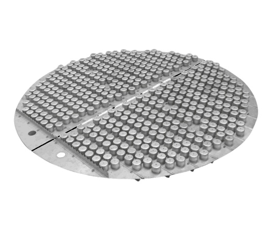
metal bubble cap tray
Metal Bubble Cap Tray For Chemical Industry
Bubble cap trays are used primarily in applications with very low liquid loading and very high flexibility, where large turndown ratios are required.  A bubble cap has riser or chimney fitted over each hole, and a cap that covers the riser. The cap is mounted so that there is a space between riser and cap to allow the passage of vapor. Vapor rises through the chimney and is directed downward by the cap, finally discharging through slots in the cap, and finally bubbling through the liquid on the tray.      
Metal Bubble Cap For Chemical Industry
Bubble cap tray is a flat perforated plate with risers (like pipes) around the perforations, and caps in the form of inverted cups over the risers.The caps are usually equipped with slots or holes through which vapor comes out. The cap is mounted so that there is a space between riser and cap to allow the passage of vapor. Vapor rises through the riser and is directed downward by the cap passing through slots in the cap, and finally bubbling through the liquid on the tray. As vapor has to pass through many passages this lead to higher pressure drop and lower capacity than other conventional trays. Liquid and froth are filled on the tray to a depth at least equal to the weir height or riser height, giving the bubble-cap tray a unique ability to be used for reaction applications.      
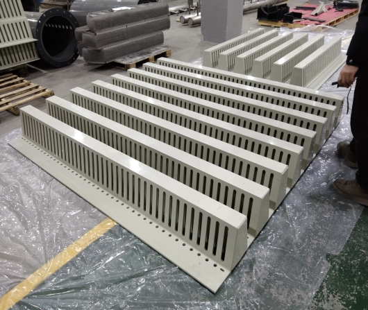
Plastic Hump support for Packed Towers & Columns
Plastic hump supports (also called packing support grids or bed limiters) are essential components in packed columns and distillation towers, designed to distribute weight evenly and prevent packing material (such as Pall rings, Raschig rings, or structured packing) from collapsing or blocking the column's lower sections. Key Features of Plastic Hump Supports Material: Made from PP (Polypropylene), PVDF (Polyvinylidene Fluoride), or CPVC, selected for chemical resistance. Design: A wave-like (hump) or grid-pattern structure that allows high open area (60-90%) for optimal fluid flow. Function: Supports the weight of packing media to prevent breakage. Ensures uniform gas and liquid distribution. Prevents packing from falling into the lower part of the column. Corrosion Resistance: Suitable for acidic, alkaline, and organic chemical environments. Lightweight & Easy to Install: Far more durable than metal supports in corrosive conditions. Applications 1. Chemical & Petrochemical Industry Distillation, absorption, and scrubbing columns for: Sulfuric acid, nitric acid, and hydrochloric acid processes. Gas treatment (H₂S, CO₂ removal). Solvent recovery in pharmaceutical & agrochemical industries. 2. Water & Wastewater Treatment Scrubber towers for removing ammonia, chlorine, and VOCs. Cooling tower packing support to maximize heat transfer efficiency. 3. Air Pollution Control Used in flue gas desulfurization (FGD) systems to hold random packing. Odor control scrubbers for industrial emissions. 4. Oil & Gas Industry Glycol dehydration towers (natural gas processing). Amine sweetening units (removing H₂S & CO₂).
Trough Type Liquid Distributor
Trough Type Liquid Distributor Uneven liquid distribution often leads to channeling and wall flow, severely reducing the efficiency of your packed tower. Our Trough Type Liquid Distributor, a critical tower internal, utilizes a classic multi-stage gravity flow design (primary trough + secondary trough) to evenly spread the inlet liquid across the entire packing surface. With extremely low pressure drop and excellent anti-fouling capabilities, it effortlessly handles complex media with trace impurities or high viscosity, ensuring optimal gas-liquid mass transfer under all operating conditions. We offer comprehensive custom solutions directly from drawings, with a flexible MOQ of just 1 set. Feel free to provide your specific process parameters for a non-standard design.
Metal Chevron Demister
Metal Chevron Mist Eliminator Engineered with precision-stamped V-shaped vanes, this eliminator captures entrained liquid droplets (≥5μm) via inertial impaction. Reducing outlet mist carryover to <50mg/Nm³, it effectively protects downstream compressors and piping from corrosion. Performance Efficiency: >99% (≥5μm) Max Temperature: 200°C Low Pressure Drop Design Materials & Build SS304 / SS316L / Duplex Hastelloy / Titanium Alloys Precision Robotic Welding Flexible Supply: MOQ starts from 1 Unit | Lead Time: 7 Days (Standard) | Support: Lifetime Technical Guidance
Others
bio ball filter
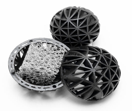
Plastic Bio Ball Packing for Water Treatment
It was invented by Jaeger Tri. Generally speaking, No big surface area is Tri-pack's biggest advantage. The distinctive shaping of ribs, struts and drip rods gives Tri-Packs tower packing media superior wetting characteristics, and the ability to maintain uniform liquid distribution throughout the bed. In the traditional theory of mass transfer, we often think big surface area will increase the mass transfer efficiency. Sometimes, Excess surface area can impede gas/liquid contact and create higher pressure drops,. Finally, it will lead to Packing's channel blocking.Based on this new understanding, Jaeger had invented Tri-pack.  Basically this pack provides maximum surface contract between the gas and the scrubbing liquid by facilitation through continuous formation of droplets by the packed bed. It was recognized best packing in for air stripping,degasifier and scrubber    
MBBR packing for water treatment
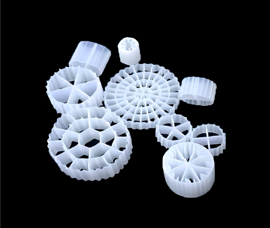
Plastic MBBR for Water Treatment
It is a type of wastewater treatment process that was first invented by Prof.Hallvard  Degaard at University of Science and Technology in the lates of 1980s.The MBBR system consists of an aeration tank (similar to a activated sludge tank) with special plastic carriers that provide a surface where a biofilm can grow. The carriers are made of a material with a density close to the density of water (1 g/cm3). An example is high-density polyethylene (HDPE) which has a density close to 0.95 g/cm3. The carriers will be mixed in the tank by the aeration system and thus will have good contact between the substrate in the influent wastewater and the biomass on the carriers    
igel ball
Plastic Igel Ball for Water Treatment
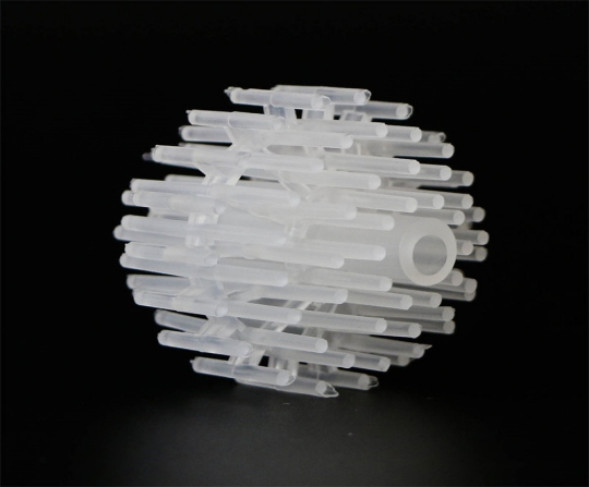
Igel ball is a common biofilter material, which mainly uses polypropylene as raw material and is processed into a prickly multi needle plastic ball by injection molding process. The small cylindrical body is evenly distributed in the ball, increasing the distribution point of vapor and liquid, so that it can fully disperse vapor and liquid.      

Welcome To Fxsino

1998
Company Founded in
  • 18000
    0+

    square meters

  • 168
    0+

    Country of Cooperation

  • 24*7
    24*7

    Mass transfer&separation design manufacturing comprehensive solution

Latest News

News
  • 132026-11
    packing tower pressure drop calculation
        Figure 1: The GPDC chart — still the fastest way to run a packing tower pressure drop calculation before committing to a purchase. How to Estimate Pressure Drop in a Random Packed Bed Before You Buy A packing tower pressure drop calculation is the gatekeeper between a good separation and a failed one. Too high, and the fan or vacuum system can't deliver the required flow. Too low, and you may have oversized the tower or overpaid for premium packing. The good news: you can estimate pressure drop accurately enough for procurement using published correlations, a process datasheet, and 30 minutes of engineering time. This guide walks through the method that most tower designers actually use in practice. Engineer's Brief: Pressure drop in a random packed bed is not a single number — it's a curve. It starts low at dry conditions, rises gradually as liquid loads the bed, then climbs steeply as you approach flood. Your operating point should sit well below the flood curve, typically at 40–70% of flood capacity depending on service. 1. The GPDC Method — Industry Standard for Good Reason The Generalized Pressure Drop Correlation (GPDC), originally developed by Eckert and later refined by Norton (now Koch-Glitsch) and others, remains the most widely used tool for random packing pressure drop estimation. It works because it normalizes the key variables into dimensionless groups that collapse diverse data onto a single chart. 1.1 The key variables • F-factor (F): F = u √(ρG), where u is superficial gas velocity (m/s) and ρG is gas density (kg/m³). This captures the kinetic energy of the vapor phase. • Liquid-to-gas ratio (L/G): Mass flow ratio of liquid to gas, adjusted by the square root of density ratio: (L/G) √(ρG/ρL). • Packing factor (Fp): A characteristic of each packing type and size, combining surface area and void fraction. Lower Fp = lower pressure drop. • Viscosity correction: For gases with viscosity significantly different from air, a correction factor μ0.1 is applied. 1.2 Reading the GPDC chart On the GPDC chart, the x-axis is the liquid-to-gas ratio term and the y-axis is the pressure drop parameter: ΔP × (ρG / (ρL - ρG) × μ0.1). The flood curve typically sits at a y-value around 0.1–0.15 depending on the specific chart version. Operating points plot as dots; their vertical position relative to the flood curve tells you the margin. Figure 2: Packing factor (Fp) values for common random packing — the lower the number, the lower the pressure drop at the same duty. 2. Step-by-Step Calculation Procedure Step 1 — Gather process data: Gas flow rate, liquid flow rate, gas density, liquid density, gas viscosity, operating temperature and pressure, tower diameter. Step 2 — Select packing: Choose type and size based on service (corrosion, fouling, efficiency needs). Record the packing factor Fp from the vendor datasheet. Step 3 — Calculate superficial velocity: u = QG / (π × D²/4), in m/s. Step 4 — Calculate F-factor: F = u √(ρG). Step 5 — Calculate L/G ratio term: (L/G) √(ρG/ρL). Step 6 — Apply GPDC or vendor equation: Plot on chart or use the vendor's curve-fit equation (many publish ΔP = A × FB × (L/G)C for specific packings). Step 7 — Check flood margin: Compare operating point to flood curve. Aim for 40–70% of flood capacity. Step 8 — Multiply by bed height: Total ΔP = ΔP per meter × bed height (m). Step 9 — Verify fan/vacuum capability: Confirm the system can deliver the required flow at the calculated pressure drop. 2.1 Worked example (simplified) A 1.5 m ID scrubber with 50 m³/h gas (ρG = 1.2 kg/m³) and 10 m³/h water (ρL = 1000 kg/m³). Using 50 mm metal Super Raschig rings (Fp ≈ 28 m⁻¹): • u = 50 / (π × 0.75²) ≈ 28.3 m/h = 0.00786 m/s — wait, recalculate: 50 m³/h ÷ 1.767 m² = 28.3 m/h = 0.00786 m/s. That's unusually low. Let's use a more realistic 5,000 m³/h: u = 5000/1.767 = 2830 m/h = 0.786 m/s. • F = 0.786 × √1.2 = 0.861 kg0.5/(m0.5·s). • L/G mass ratio = (10×1000)/(5000×1.2) = 10000/6000 = 1.67. • (L/G) √(ρG/ρL) = 1.67 × √(1.2/1000) = 1.67 × 0.0346 = 0.058. • From GPDC for Fp = 28: at F = 0.86 and L/G term = 0.058, expect roughly 80–120 Pa/m depending on liquid rate. • For a 4 m bed: total ΔP ≈ 320–480 Pa — well within fan capability. 3. Common Mistakes That Kill Accuracy Mistake Why it hurts The fix Using dry pressure drop only Ignores liquid holdup, the #1 driver of ΔP in service Always calculate at operating L/G ratio Wrong packing factor Generic Fp tables don't match modern high-performance packings Use vendor-specific Fp or equivalent data Ignoring viscosity High gas viscosity (e.g. ethylene at pressure) shifts the curve Apply μ0.1 correction for non-air gases Overlooking distribution quality Poor distribution creates channeling that locally spikes ΔP Factor in distributor performance No flood margin check Operating too close to flood causes ΔP to spike unpredictably Stay below 70% of flood capacity Forgetting bed height Per-meter ΔP looks fine but total ΔP exceeds fan rating Always multiply by actual bed height 4. FAQ Q1: How accurate is the GPDC method for procurement decisions? A: ±15–20% when using vendor-specific packing data and correct process conditions. That's sufficient to size fans, select packing, and confirm bed height. For final hydraulic guarantee, use vendor software with measured curves. Q2: Can I use the same calculation for structured packing? A: The GPDC is calibrated for random packing. Structured packing uses different correlations — typically based on specific surface area and crimp angle. Use the structured packing performance factors guide for those cases. Q3: What if my calculated ΔP is too high? A: Options in order of preference: (1) increase tower diameter, (2) switch to a lower-Fp packing (e.g. larger size or different geometry), (3) reduce bed height by accepting more stages elsewhere, (4) accept higher fan power. Never ignore it — high ΔP at design is a guarantee of poor operation. Need a Pressure Drop Estimate for Your Tower? FXSINO supplies performance data for metal Super Raschig rings, Pall rings, saddles and other random packing with vendor-specific Fp values and GPDC curves. Send your process datasheet — we'll run the packing tower pressure drop calculation and recommend the right packing and bed height. Email: jackieqiu9202@gmail.com  |  +86 18507999558  
    Read More
  • 062026-11
    Ceramic Structured Packing vs Random Packing: Which One Actually Pays Off
      Figure 1: Ceramic structured modules vs. ceramic random rings — same material family, very different cost and performance profile. Ceramic Structured Packing vs Random Packing: Which One Actually Pays Off The ceramic structured packing vs random packing debate is usually framed around HETP and surface area. That's the wrong lens. Both are ceramic, so they share acid resistance and high-temperature capability. The real question is total cost: what you pay up front, what you lose to pressure drop every year, and how often you'll have to open the tower. Below is the engineering-economics view, not a catalogue. Engineer's Brief: Structured ceramic buys efficiency and pressure-drop margin. Random ceramic buys robustness and low maintenance cost. The crossover isn't about "which is better" — it's about whether the energy and footprint savings of structured packing repay its premium before the next turnaround. 1. Pros and Cons on the Same Duty Dimension Ceramic Structured Packing Ceramic Random Packing Efficiency (HETP) 0.2–0.5 m (250Y class) 0.6–1.2 m Pressure drop Low (15–50 Pa/m typical) Higher (50–200 Pa/m typical) Bed height for same stages ~40–60% of random Baseline (taller tower needed) First cost (material + install) 3–5× random (reference) Lowest ceramic option Fouling / solids Sensitive — ordered channels plug Tolerates solids far better Cleaning & replacement Hard to clean in place; modules scrap if cracked Dump, wash, reload through manway Service life 15–25 yr (clean service, reference) 5–15 yr; easy top-up Distribution sensitivity Demands ≥90 drip pts/m², level discs More forgiving of maldistribution Best fit Vacuum, hot acid, high-purity split Scrubbers, drying towers, dirty gas Generic reference values; HETP and ΔP vary with system, F-factor, L/G and ceramic grade. Replace with FXSINO project data before publication. Figure 2: A structured ceramic bed depends on the support grid and distributor around it — the packing alone doesn't deliver the curve. 2. Total Cost Breakdown (Not Just Unit Price) Split the decision into five cost buckets: 2.1 First cost • Structured ceramic: higher material cost plus module fabrication, plus careful installation (alignment, soft pads, bed limiter). • Random ceramic: cheaper per m³, dumped in lifts, simpler labor. For a DN2000+ tower, the random install saving alone can be meaningful. 2.2 Energy cost (the hidden one) •ceramic structured packing can run 30–50% lower ΔP than ceramic random at similar duty. In a fan- or vacuum-driven column, that's a direct electricity bill every hour of every year. • In vacuum distillation, lower ΔP also means lower reboiler temperature — additional 10–20% energy relief in some duties. • Rule of thumb: if the fan/vacuum energy saving repays the premium in 3–5 years, structured wins. Beyond 6–8 years, random is usually cheaper on life-cycle. 2.3 Footprint and shell cost • Structured reaches the same number of theoretical stages in roughly half the bed height. On a new column, that can shrink shell length, support steel and foundation cost. • On a retrofit, the shorter bed frees space for a better distributor or an intermediate redistributor. 2.4 Maintenance and downtime • Random: open manway, vacuum out fouled rings, power-wash, reload. Hours of labor, no scrap. • Structured: if it plugs, you often can't clean it effectively in place; unloading risks chipping brittle modules. A fouling-prone service can turn the premium into a liability. 2.5 Lifespan and replacement frequency • Ceramic itself is durable — no corrosion, no polymer aging. In clean acid service, structured modules can last 15–25 years (reference range). • Random rings may need partial top-up every few years from breakage during handling, but full-bed replacement is cheap and fast. 3. When Each One Actually Pays Off Choose ceramic structured when… • Vacuum column where every mbar of ΔP costs reboiler duty. • Hot corrosive split (H₂SO₄, HCl, SO₂/NOₓ, organics) above what metal alloys tolerate economically. • Clean gas, particulate <20 mg/Nm³, no crystallization or polymer. • Tower is hydraulically limited and you need capacity without a new shell. • Continuous operation with a long amortization horizon (5+ yr run). Choose ceramic random when… • Scrubbers, drying towers, quench towers with dust, slurry mist or scaling. • Column diameter <1 m — structured premium hard to justify. • Intermittent operation or frequent turnarounds. • Low liquid rate isn't critical and HETP of 0.6–1.2 m is acceptable. • Budget-constrained retrofit where first cost dominates the business case. Hybrid — the move nobody talks about In dirty-inlet absorption columns, put 1–2 m of ceramic random packing (or super Raschig/saddle) at the foul inlet zone, then structured 250Y above it. You protect the expensive module from plugging and keep the efficiency where it matters. This often beats either pure option. 4. FAQ Q1: How fast does the structured premium pay back? A: For a continuous, energy-intensive column, often 1.5–5 years through ΔP and reboiler savings. For an 8,000 h/yr scrubber the payback shortens; for a 2,000 h/yr intermittent tower it can stretch past 6–10 years, where random wins. Q2: Can structured ceramic handle fouling service if I just clean it? A: Poorly. Ordered channels plug fast, and in-place cleaning is ineffective. If you expect scaling or solids, use random — or the hybrid layout. Don't buy structured and hope for the best. Q3: Is the longer lifespan of structured ceramic real? A: In clean, non-thermal-shock service, yes — 15–25 year reference life is achievable. But a single bad heat-up, vibration-induced chipping, or HF-containing medium can destroy that advantage. Lifespan depends on duty discipline, not just the material. Size the Right Ceramic Bed for Your Column FXSINO manufactures ceramic structured packing (125Y–500Y, porcelain/alumina/SiC), ceramic random rings and saddles, plus the support grids and distributors that make either choice perform. Send duty, medium, temperature and run-hours — we return a total-cost comparison, not just a quote. Email: jackieqiu9202@gmail.com  |  +86 18507999558
    Read More
  • 062026-11
    How to Install Random Packing in a Packed Column: Step-by-Step Guide
      Figure 1: Controlled random packing loading with level bed surface — the core of any reliable tower packing installation guide. How to Install Random Packing in a Packed Column: Step-by-Step Guide This tower packing installation guide focuses on the field work that decides whether a random packed bed actually performs: preparing the column, controlling free fall height, setting the top screen or bed limiter, and running settling and commissioning checks. Material selection matters, but a perfectly specified packing can still fail if it is dumped, crushed, or left uneven during installation. Engineer's Brief: Random packing is designed to form a self-randomizing bed. The installer's job is not to arrange it — it is to protect the void fraction, keep the bed level, and avoid impact damage. Most "packing problems" found six months later (high ΔP, channeling, local flood) are really installation problems made on day one. 1. Tower Preparation Before Any Packing Enters A clean, level, verified shell is the foundation of the whole job. Skipping prep to save a shift almost always costs more later. 1.1 Internal cleaning • Remove all welding slag, cutting oil, rust scale, bolts, insulation fragments and plastic wrapping. • New metal packing may carry machining oil — for air-separation, oxygen service or alkaline systems, de-oil before loading. • Ceramic packing should be screened to remove transport breakage before it enters the bed. 1.2 Support grid verification • Grid must be level, secure, and mechanically sound — no loose panels, no blocked openings, no deflecting beams. • Opening size must retain the smallest packing element. If gaps are too large, add a retention layer (larger random packing, perforated plate, or fine mesh pad) below the main bed. • Confirm free area is consistent with the hydraulic design — the support is the first flow restriction in the column. 1.3 Mark bed elevations • Mark every bed interface on the shell or internal reference weld. • Weight tells you how many bags to load; elevation tells you when to stop. Both must be tracked. • For multi-bed columns, confirm which packing goes in which zone before any bag is opened. 2. Free Fall Height and Loading Method Free fall height is the single most abused variable in random packing jobs. Dropping packing from the manway looks fast — and it quietly breaks ceramic, dents thin metal, and nests plastic into low-void clumps. Method Typical use Drop height control Key benefit Dry loading (chute / bag / soft shoot) Small–mid towers, all materials Keep drop low; general field reference ≈ ≤1 m, tighter for ceramic/thin-wall metal Simple, no water handling Wet loading (water-filled column) Ceramic, thin-wall metal, large towers Pack settles through water; water level kept above bed Less breakage, more uniform bed, better void fraction Mechanical conveying Very large beds, high volume Controlled feed rate, distributed discharge Consistent density, less manual labor Drop-height values are general field references, not universal code; confirm against packing material, wall thickness and project specification. • Never stand directly on the packing. Use spreader boards if entry is required, and remove them before closing. • Feed from multiple points around the cross-section; do not pile in one spot and let it spread. • Do not compact. The target is natural settled density, not "as much weight as possible." • Level the surface every 1–2 m of bed growth with a sweep board — never tamp. Figure 2: Top screen / bed limiter sitting just above the packed bed — restrains packing without compressing the void fraction. 3. Top Screen, Bed Limiter and Distributor Reset Once the bed reaches design elevation, the top of the packing needs restraint — but not pressure. • Top screen / mesh: Used when small elements could lift into the distributor. Mesh aperture must be smaller than the packing feature but open enough to avoid adding pressure drop. • Bed limiter / hold-down grid: Fixed to the wall with a small clearance above the bed (commonly referenced around 20–50 mm). It stops uplift during surges without crushing the top layer. • No heavy compression: A weighted plate sitting on the bed destroys the void fraction and creates a high-ΔP zone right under the distributor. • Reinstall distributor: Center it, confirm level, verify orifices are clear, and check impingement protection on the feed pipe. 4. Step-by-Step Installation Sequence Step 1 — Confined-space release: Lock-out/tag-out, purge, atmosphere test, permit signed. No exceptions. Step 2 — Shell inspection: Clean, dry, no debris. Document support grid condition with photos. Step 3 — Verify support: Level grid, correct opening size, retention layer in place, secure fixation. Step 4 — Mark elevations: Identify every bed interface and target height on the shell. Step 5 — Control drop height: Use chutes/bags/wet loading; keep impact low and distribution even. Step 6 — Load in lifts: Add packing in layers, level every 1–2 m, track weight vs. elevation. Step 7 — Final leveling: Smooth the top surface; no high spots, no trenches to the wall. Step 8 — Install top restraint: Place screen / bed limiter with correct clearance; secure fixings. Step 9 — Reset internals: Distributor, redistributors, collector trays, manways. Step 10 — Settling & commissioning tests: See below. 5. Settling Tests and Commissioning Checks Installation is not finished when the manway closes. You need a baseline before the column sees real service. 5.1 Settlement observation • After loading, allow the bed to settle; re-check bed elevation against the mark. • If the surface drops below target, top up before installing the limiter. • Record final bed height — this is the reference for future turnaround inspections. 5.2 Dry / water test • Run gas-only or air-water test at low load first. • Watch distributor spray pattern, check for dry zones and wall flow. • Measure baseline ΔP across the bed at known flow — deviations vs. design indicate nesting, blockage or uneven loading. 5.3 Ramp to design • Increase vapor and liquid load gradually; pre-wet the bed before normal reflux. • Log ΔP vs. load. A sharp knee earlier than expected = hidden restriction or over-dense bed. • Confirm separation efficiency against a known feed/composite sample before declaring success. 6. FAQ Q1: Can I just dump random packing from the top manway? A: Not if you want the bed to perform. High free-fall breaks ceramic, dents thin metal, and nests plastic. Use chutes, bags, or wet loading and keep the drop height controlled. Q2: Do I need a top screen or is a bed limiter enough? A: It depends on packing size and service. Small elements or surge-prone columns may need mesh; larger packing usually only needs a hold-down grid. The rule is: restrain movement without compressing the bed. Q3: Why does bed leveling matter so much? A: An uneven surface sends liquid to the low side and gas to the high side. The result is channeling and 30–50% efficiency loss even with perfect packing. Level every lift. Q4: How do I know the installation actually worked? A: Baseline ΔP at low load, even distribution in the air-water test, stable bed height after settling, and on-spec separation at ramp-up. No baseline = no proof. Need a Packing + Internals Package That Installs Cleanly? FXSINO supplies random packing (metal super Raschig, Pall rings, saddles), support grids, distributors and bed limiters dimensioned to your tower ID and service. Send tower data and we return a loading plan with drop-height, bed-height and restraint details. Email: jackieqiu9202@gmail.com  |  +86 18507999558
    Read More

leave a message

leave a message
If you are interested in our products and want to know more details,please leave a message here,we will reply you as soon as we can.
submit

Home

Products

whatsApp

contact