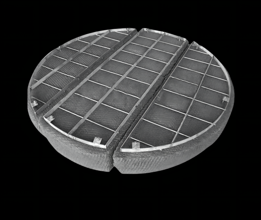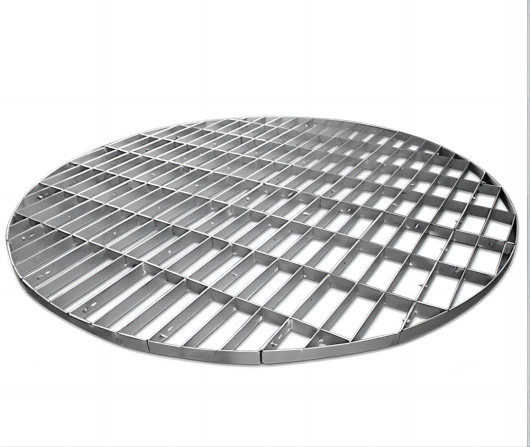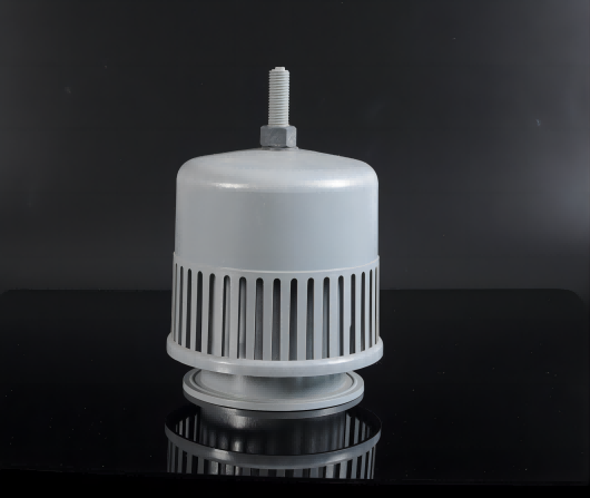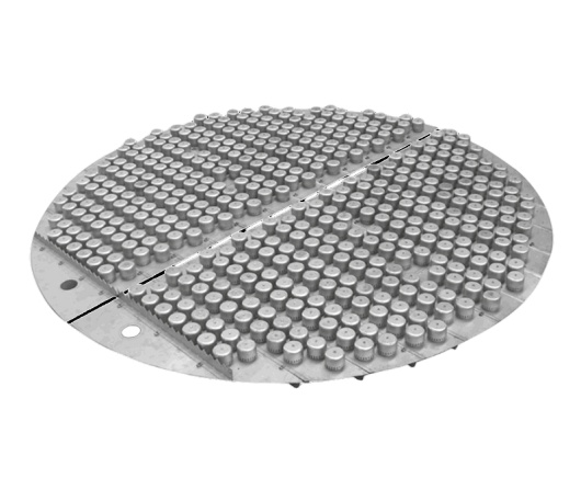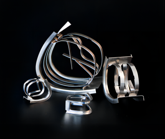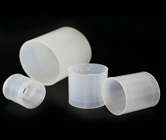

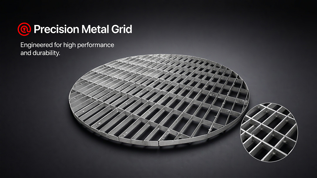
Figure 1: Support grid is the foundation of the packed bed — if free area is lower than the packing void fraction, the grid itself becomes the flooding point.
Engineer's Brief: A support grid must do three things at once — carry the bed weight, let gas through without becoming a bottleneck, and keep packing from dropping. Rule of thumb: free area of the grid must exceed the void fraction of the packing above it. Plain bar grating works for clean random packing; camel-hump (beam-type gas-spray) support is the better choice for DN1500+ towers, high liquid rate or dirty service. FXSINO fabricates support grids to tower ID, packing type and project load data — not catalog "fits all" plates. [10](@ref)
Welded bars or punched plate strips. Cheap, simple, good for small towers and clean service. Free area typically 80–90%; gas comes straight up through gaps so it can channel at the bed bottom if gaps are uneven.
Punched holes or slots. Only for larger packing or with overlay mesh — small orifices clog in fouling service. Not ideal as primary support for fine random packing.
Arched beams with side gas ports and bottom liquid clearance. Gas enters sideways into the bed, liquid drops through the bottom gap — two separate paths, so less entrainment and lower ΔP. Standard for DN1500+ scrubbers, desulfurizers and high-L absorption columns. [7,13](@ref)
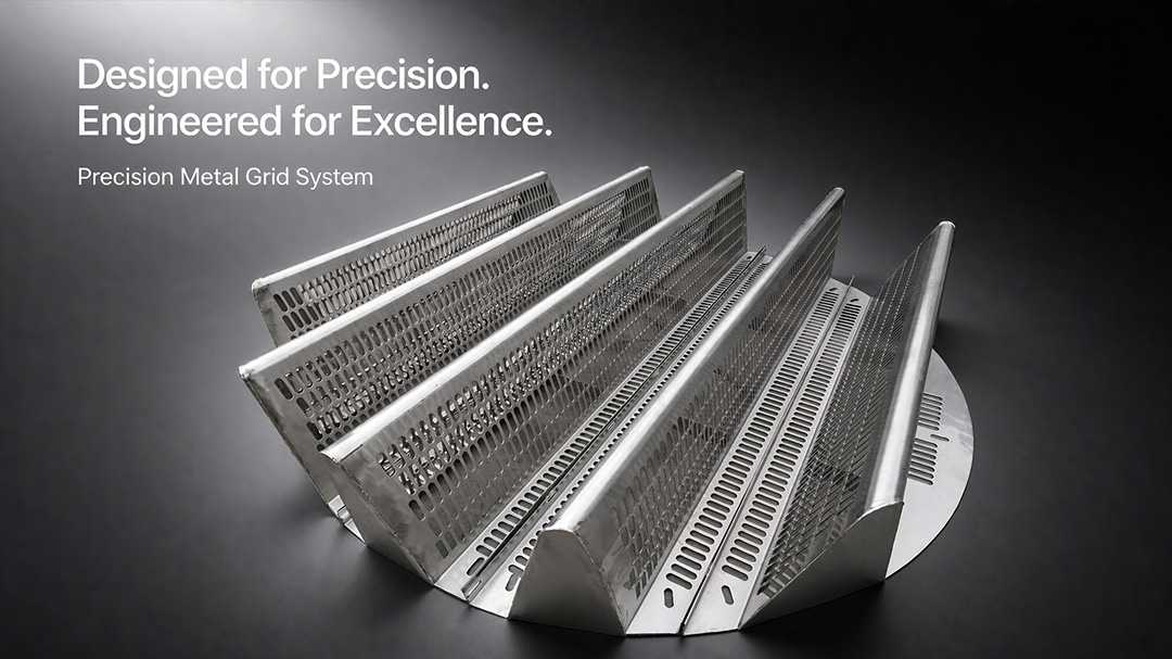
Figure 2: Beam-type support — gas from side ports, liquid from bottom clearance; modular beams assemble through the manway.
| Parameter | Rule / reference value | Why it matters |
|---|---|---|
| Free area | ≥80% random / 90–95% structured | Must exceed packing void fraction [1,11](@ref) |
| Load rating | bed weight + hold-up × SF ≥1.5 | Ceramic beds need reinforced beams [1](@ref) |
| Opening size | < min packing dimension | Prevent drop-through / add mesh overlay [12](@ref) |
| Levelness | ≤3 mm/m (project spec wins) | Tilt → wall flow / maldistribution [6](@ref) |
| Grid ΔP | low-resistance design target | Camel-hump ~60–200 Pa typical [13](@ref) |
| Material | CS / 304 / 316L /双相 / Ti | Match column atmosphere + liquid |
Values are generic design references; final free area and beam stress must come from FXSINO project calculation against your packing bulk density and bed height. [10](@ref)
Total face load on the grid:
Beam deflection limit is usually ≤ L/300. Undersized grid sags, packing surface dips, liquid pools at the low side. [1](@ref)
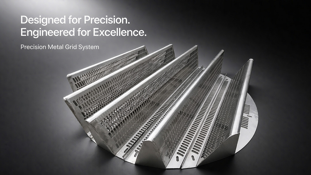
Figure 3: After unloading packing — check support ring weld, beam deflection and corrosion at wall interface before reusing the grid.
• Lock-out/tag-out, depressurize, drain liquid.
• Purge / wash if medium is acidic, toxic or fouling.
• Remove packing from top down — don't dig from bottom, don't stand on the grid.
• Vacuum fines and broken fragments; check if small packing dropped through gaps.
• Support ring / ledge: corrosion, weld crack, level continuity.
• Shell interface: gap where slurry can sit → crevice corrosion.
• Beam sag: straight edge across span; >3 mm/m is a re-level or replace signal. [6](@ref)
• Old gasket / sealant: remove before new grid seats.
• Modular camel-hump beams: enter through manway, seat on support ring, align locating lugs.
• Grating sections: symmetric placement, no forced fit, uniform seam gaps.
• Level check with spirit level on a straight edge — correct with shims, not by bending bars.
• Bolt / tack weld per drawing; for corrosive service use continuous weld or sealed gasket at wall. [3](@ref)
• Confirm distributor drops line up with grid free area, not on a beam.
• Dump packing evenly, don't pile one side.
• If bed is deep, set bed limiter and intermediate redistributor before closing.
• Start with gas only, low load — watch ΔP trend.
• Ramp liquid gradually; sudden full-rate flood can lift light grids.
• Compare ΔP vs design; if high at low load → grid still restricted or distributor misaligned.
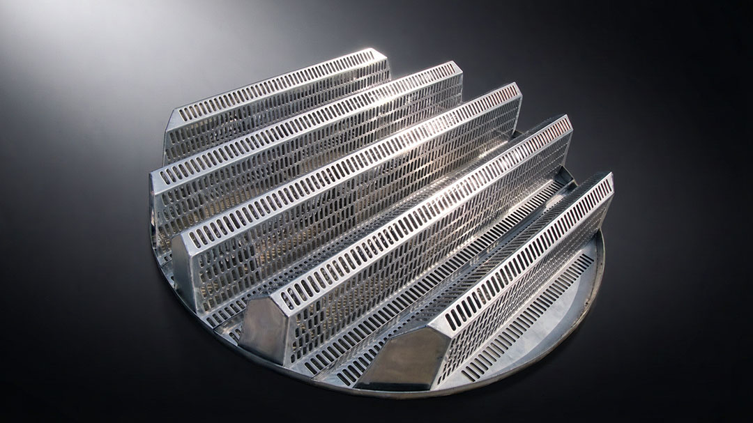
Figure 4: Grid seated, leveled and shimmed on the support ring — verify free area is not blocked by the shell weld or distributor stub.
| Type | Free area | Fouling | Bed load | Use case |
|---|---|---|---|---|
| Bar grating | 80–90% | Medium | Moderate | Small tower, clean random packing |
| Perforated plate | 60–80% | Poor | High | Large packing / overlay mesh |
| Camel-hump beam | ≥90% [10](@ref) | Good | High | DN1500+ scrubber, desulfurizer |
| PP/RPP grid | 80–90% | Good | Light | Cool corrosive wash tower |
Q: Can I reuse the old grid when changing packing?
A: Only if free area still exceeds the new packing void fraction, beams are level within spec, and welds are sound. Moving from 50mm rings to 25mm or structured packing often forces a grid change — gaps are too wide or free area too low.
Q: Why is my ΔP high right above the grid?
A: Classic sign the grid is the bottleneck — side port blocked, bottom clearance bridged with scale, or plate free area < packing void. Camel-hump retrofits usually drop ΔP 30–50% in that zone.
Q: Do I need a bed limiter above the support grid too?
A: Not at the bottom — the grid already holds the bed. A hold-down plate goes at the top of the bed to stop fluidization or lift under high vapor velocity.
FXSINO is a manufacturer of packed-column internals — camel-hump support grids, bar grating, plastic random packing, metal packing, distributors, bed limiters and redistributors. We run free structural load calculation per project and supply laser-cut, level-tested grids for manway assembly. [10](@ref)
Email: jackieqiu9202@gmail.com | +86 18507999558
 Address : Intersection of Jinguang Avenue and Chongqing Middle Road, Anyuan Industrial Park, Anyuan District, Pingxiang City, Jiangxi
 Tel : +86-18507999558
 Email : sales@fxsino.com
 WhatsApp :
+86-18507999558
 IPv6 network supported Sitemap | XML | Blog | Privacy Policy